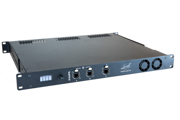
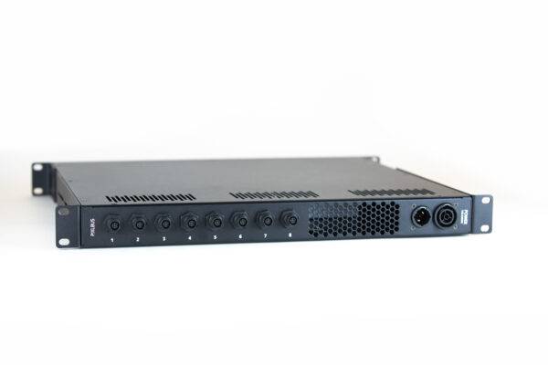
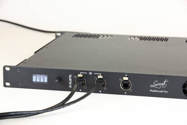
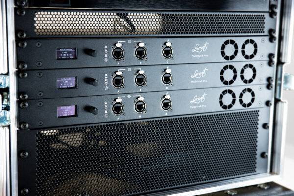
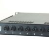
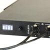
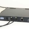
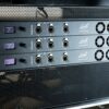
Lucenti PixlDrive8 Pro is an 8 channel PixlBus controller and LED driver with an integrated PSU and KLUSTR technology natively on board. The unit features 8 PixlBus outputs, each of them offering 200W/24Vdc and support data and power. The ports can be enabled or disabled individually and support hot-plugging of other devices.
GENERAL
- Product name: PixlDrive8 Pro Controller
- Description: 8 channel PixlBus controller: integrated PSU, KLSTR and Lucenti technology
- PN: BW-LU-PD8
PIXEL OUTPUT
- Outputs
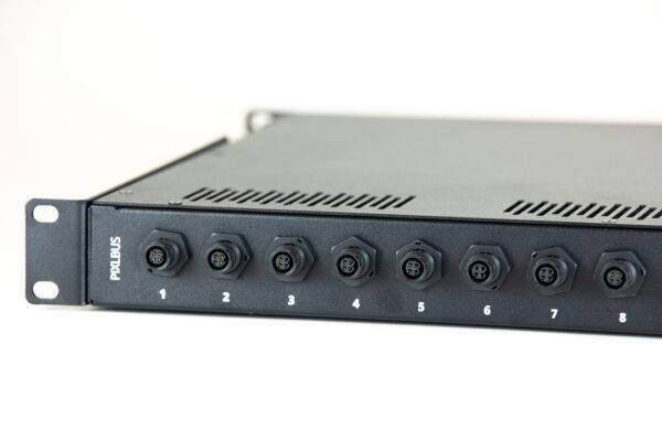
– 8x PixlBus output ports (data + power), 200W/24Vdc per port. Only supports PixlBus devices.
– 400 RGBW pixels per port (= 8x BW-100, 16x BW-50, …) @ 50Hz. 3200 RGBW pixels in total. Protocol limit for 400x RGBW on one port is ~60Hz.
– Ports can be individually enabled/disabled.
– Ports support hot-plugging of devices. - Protection on outputs
– Overload protection: for sustained load > 200W. Auto cut-off for peak loads.
– Short circuit detection: port will be disabled independent of other ports. - Connector: Plastic M12 4-pin connector, push-lock
- Protocol: Proprietary Lucenti PixlBus protocol
DEVICE MODES AND CONTROL PROTOCOLS
- Supported device modes:
– eDMX (Ethernet DMX):
Art-Net I (broadcast) & II, 3, 4 (unicast)
sACN/E1.31 multicast and unicast
– Effects: Internal library of customizable effects, can run standalone
– Test Patterns: Internal library of test patterns, can run standalone
– Blackout - Supported merging modes (in Art-Net/sACN mode)
– HTP (Highest Takes Precedence)
– Merge up to 4 sources per protocol per universe - Supported mapping modes
– Manual: Start Universe
– Dense mode:
KLSTR: Automatic mapping (will be added through a future firmware update).
KLSTR TECHNOLOGY
- Discovery
– Auto discovery of multiple PixlDrive8 Pro controllers and all connected PixlBus devices
– Auto generation of DMX patch
– Easy assignation of Fixture IDs
– Link fixtures to on-board GDTF files.
– Export MVR file from KLSTR application containing all fixtures, GDTF files, fixture IDs and mapping for use in console - Synchronization:
- Packet rate and packet sync Controller can slave to incoming Art-Net or sACN packet rate. ArtSync/sACN support will be added through a future firmware update.
- Monitoring:
– Monitor multiple devices from one interface
– Get alerts of critical events (e.g. port short circuit, devices that went offline, …)
– Display sensor data (load per port, temperature, framerate) per controller - Connectivity
– IPv6 and IPv4
– Topology overview and configuration
– Topology redudancy
– – Spanning tree
– – Ethernet ports are automically bridged on failing controller
PIXLBUS TECHNOLOGY
- PixlBus protocol
– Auto discovery of devices on PixlBus, together with KLSTR discovery this allows for a fully automated setup
– Auto discovery of devices on PixlBus, together with KLSTR discovery this allows for a fully automated setup
– All PixlBus devices on one controller are synchronized.
USER INTERFACE
- Hardware
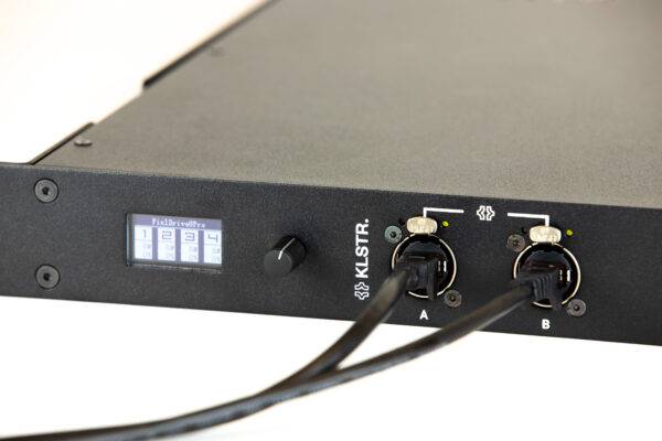
– Display: OLED single color graphical display 1,3” –
Rotary pushbutton: Rotating push button knob to control menu
– LEDs Ethernet Activity + link led - KLSTR Desktop APP
– Desktop app for Windows, MacOS and Linux
– Allows full configuration of all parameters in an intuitive interface - Webinterface: Landing page: Link to download KLSTR-CTRL app. Upload new firmware file
CONNECTIVITY
- Network: 3x Gigabit of which 1x POE (only supplying power to logic board, not to outputs)
- Power: TRUEcon 115/230Vac 50/60Hz In/Out
ELECTRICAL
- Power input
– 110-240 VAC , 50/60hz. 1m Schuko to TRUEcon cable included.
– PoE port for powering logic board (maintainance, log retrieval) - Power supply: 1600W/24Vdc, 200W per port
- Max operating temperature: min 45 ºC (ambient temperature)
- Power distribution board: Separate power distribution and voltage/current sensing board
HOUSING / MECHANICAL
- Housing: Metal housing, black powder coating, IP20 rating
- Mounting: 1U rack mountable, standard 19 inch rack compatible, front and ba
CABLING CONSIDERATIONS
- PixlBus:
– 30M in between controller and first bar and NO cable in between bars.
– NO cable in between controller and first bar and 10M in between 8 BW-100 bars.
– NO cable in between controller and first bar and 5M in between 16 BW-50 bars.
– The cable lengths might be increased when using less bars or not using full output (RGBW@Full) on all bars!

